Whether you’re a seasoned professional or a DIY enthusiast, understanding the typical dimensions of countersink tools is critical to the success of your projects. From woodwork to metalwork, countersinks are pivotal in creating seamless, flush-fitting screws and rivets. This comprehensive guide delves into the world of countersinks, providing detailed size charts and insights into their typical dimensions. Prepare to equip yourself with the knowledge needed to make informed decisions and elevate the quality of your workmanship to a whole new level.
Basic Equations
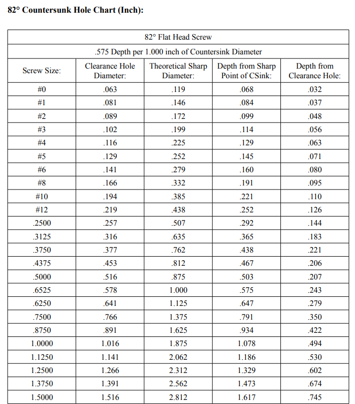
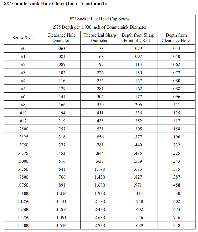
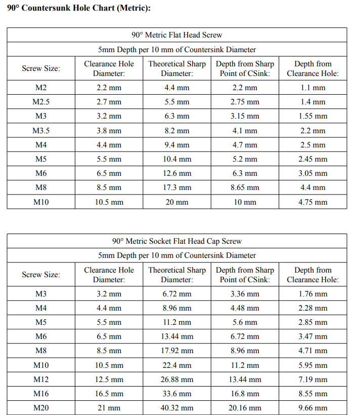
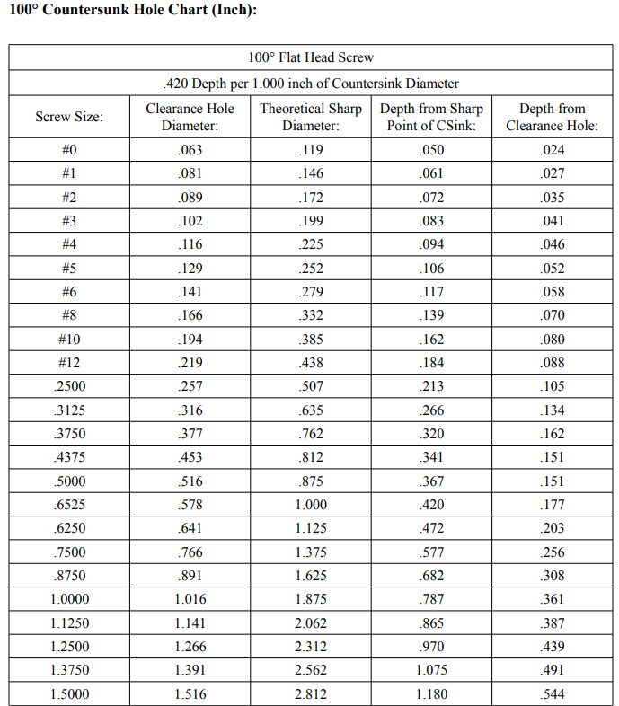
Suppose Ɵ is the included angle of the countersink. In that case, Ø is the theoretical sharp diameter of the countersunk hole, ø is the diameter of the clearance hole, and D is the depth to which the countersink must move to create the desired (Ɵ) countersunk diameter; then:
D = Ø/(2*tan(Ɵ/2)) for the Depth from the Sharp Point of Countersink, and
D = (Ø-ø)/(2*tan(Ɵ/2)) for the Depth from Clearance Hole Diameter.
1. Size Charts For Typical 82° Countersink Dimensions
| Screw Size | Drill Size | Body Diameter | Depth |
| #4 | 1/8″ | 0.332″ | 0.123″ |
| #6 | 9/64″ | 0.373″ | 0.139″ |
| #8 | 5/32″ | 0.415″ | 0.155″ |
| #10 | 3/16″ | 0.457″ | 0.170″ |
| #12 | 7/32″ | 0.498″ | 0.185″ |
| 1/4″ | 1/4″ | 0.582″ | 0.217″ |
| 5/16″ | 5/16″ | 0.665″ | 0.248″ |
| 3/8″ | 3/8″ | 0.748″ | 0.279″ |


2. Size Charts For Typical 90° Countersink Dimensions
| Screw Size | Drill Size | Body Diameter | Depth |
| #4 | 7/64″ | 0.348″ | 0.174″ |
| #6 | 9/64″ | 0.391″ | 0.196″ |
| #8 | 5/32″ | 0.435″ | 0.217″ |
| #10 | 3/16″ | 0.478″ | 0.239″ |
| #12 | 1/4″ | 0.521″ | 0.261″ |
| 1/4″ | 9/32″ | 0.609″ | 0.305″ |
| 5/16″ | 5/16″ | 0.696″ | 0.348″ |
| 3/8″ | 3/8″ | 0.783″ | 0.392″ |

3. Size Charts For Typical 100° Countersink Dimensions
| Screw Size | Drill Size | Body Diameter | Depth |
| #4 | 3/32″ | 0.368″ | 0.184″ |
| #6 | 7/64″ | 0.414″ | 0.207″ |
| #8 | 1/8″ | 0.460″ | 0.230″ |
| #10 | 9/64″ | 0.506″ | 0.253″ |
| #12 | 5/32″ | 0.552″ | 0.276″ |
| 1/4″ | 7/32″ | 0.644″ | 0.322″ |
| 5/16″ | 1/4″ | 0.736″ | 0.368″ |
| 3/8″ | 9/32″ | 0.828″ | 0.414″ |

Different Uses for Standard Countersink Angle
Here’s a basic summary of standard countersink angles for various uses. This chart includes some of the most common uses, but it’s important to note that the ideal countersink angle can vary depending on the specific application, material, and type of screw or fastener being used.
| Use Case | Standard Countersink Angle |
| Machine Screws | 82° |
| Flathead Screws | 82° |
| Wood Screws | 82° |
| Metric Screws (DIN standard) | 90° |
| Aerospace Industry | 100° |
| British Standard Whitworth (BSW) | 90° |
| American National Standard (ANS) | 82° |
| Rivets | 120° |
| American Iron and Steel Institute | 82° |
| American Standard for Aluminum | 90° |